Filament Dry Box Project
A fully 3D printed dry box for filament spools.
Please note that this project requires a lot of material and effort to assemble, and moisture can leak in over time if there are pores in the print.
Downlad STL from Thangs.com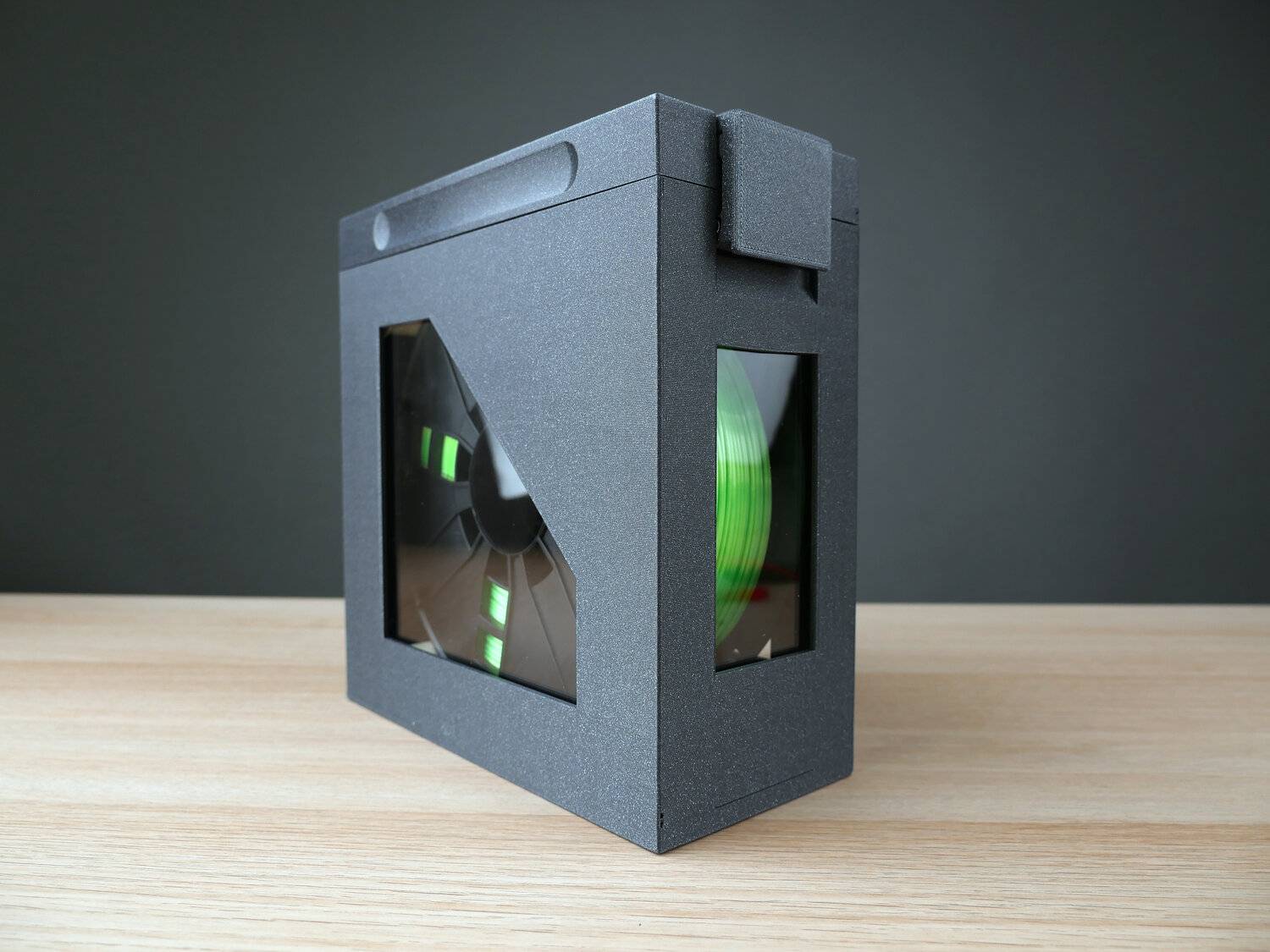
Assembled fully 3D printed filament dry box
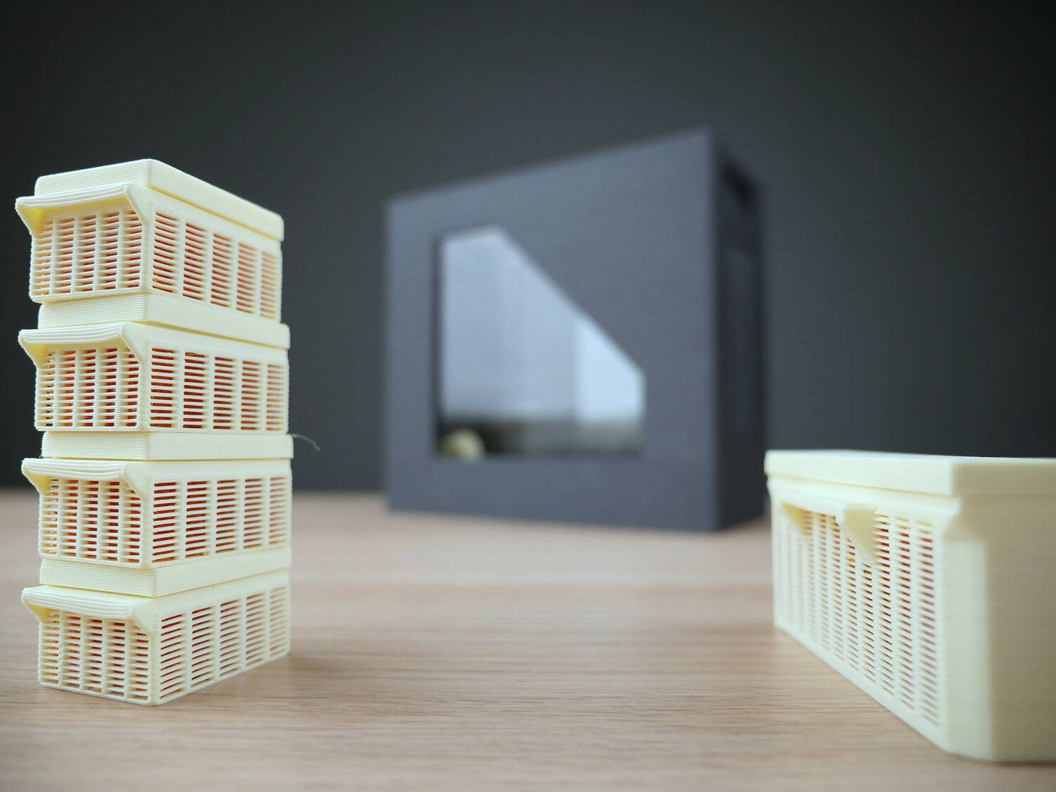
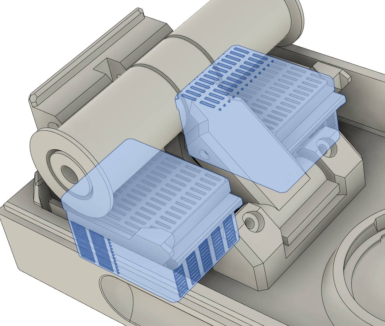
Silica gel containers for moisture absorption
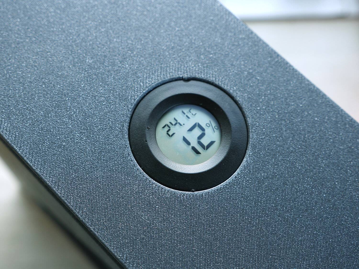
Hygrometer for humidity monitoring
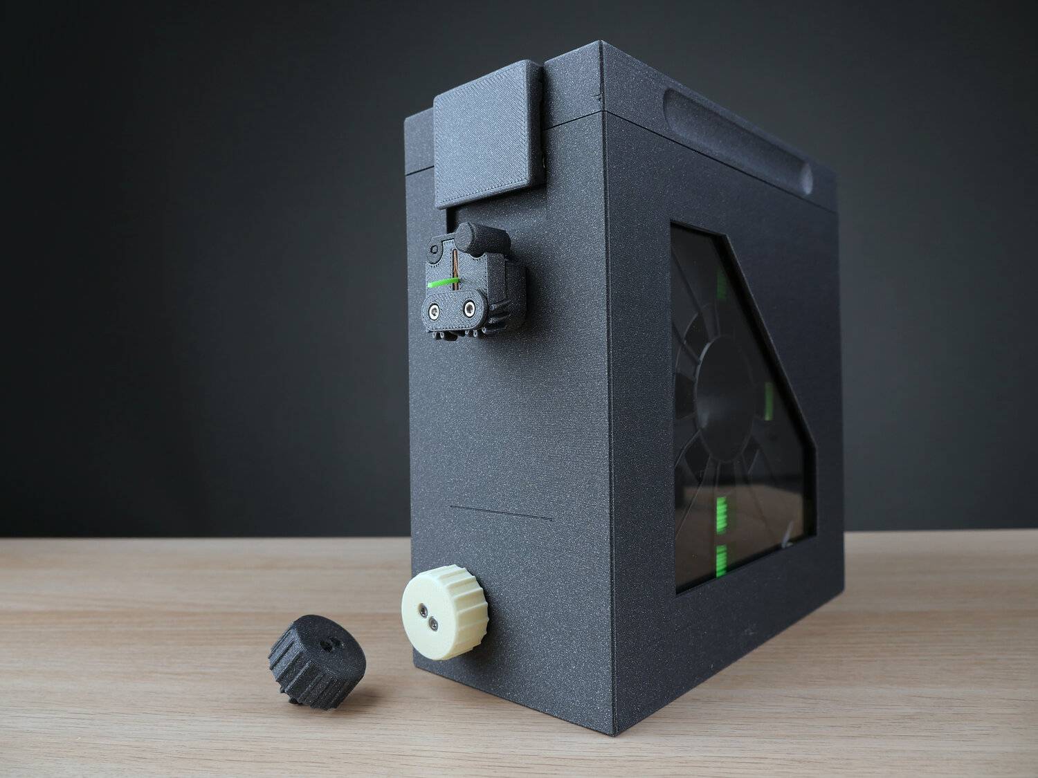
Rewind system and airtight gateway with locking mechanism
Printed in Fiberlogy Vertigo filament (no US store). PETG: UK store, DE/Europe store, FR store, IT store. PLA: UK store, DE/Europe store, FR store, IT store.
Advantages
Cool looks compared to dry boxes made out of cereal boxes or other containers.
Keeps filament dry for a while. Contrary to popular opinion, most filaments can take advantage of being dry. Fillamentum strongly recommends drying even for PLA.
Dry filament prints smoother, with less stringing, better layer adhesion and mechanical strength.
Rewind and lock mechanism to avoid opening the box or losing filament when swapping colors at the printer.
Works as a storage unit for when filament is not in use.
Integrated hygrometer helps deciding when to replace/recharge desiccant.
MMU2S support for most filaments: Filament valve was completely redesigned with a pneumatic fitting. I haven’t tested this with an MMU2S unit.
Model is free for personal use. Print the dry box with no license fees.
Make sure to check the shortcomings section below.
Spool compatibility
Made for 1Kg, ~200mm diameter spools of all widths (that I could find).
- Up to 1Kg spools
- 194 - 204 mm diameter or 7.64”-8.03” (covers common spool sizes, most around 200mm in diameter)
- 53 - 80 mm wide on the outside, covering most spools for this diameter range (including Fiberlogy’s fatter spools). One exception is the filament that comes with a Prusa MK3S printer, which is about 90mm wide.
Customization
Options for 3 window layouts or no windows.
Lid with or without hygrometer (to check humidity).
Bill of Materials
List includes affiliate links (I take a small commission at no additional cost to you). There’s a chance for the list to change. Let me know if I should add links to other Amazon stores.
BOM listPrinting
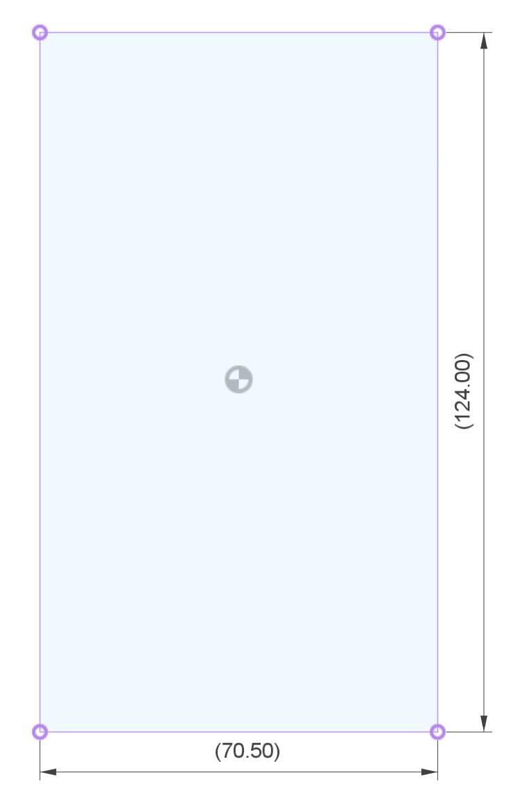
The largest piece is 220mm in length and 205mm tall. An Ender or a MK3S will work, but a mini printer such as the Prusa Mini cannot print this model.
I printed the box in the photos in Fiberlogy’s Vertigo PLA/PETG and you’ll have to find a reseller. In the US Narrow Path 3D is stocking the Vertigo filament. Similar to Fillamentum’s PLA/ASA Vertigo Grey. I’m also testing more cost effective filaments, like the ones from GTST3D Europe / GST3D US - very inexpensive, but thei filament diameter can sometimes vary wildly in my measurements (sometimes close to 1.6mm diameter) and is only PLA, although I was able to print several boxes with no issues with their PLA. Just make sure it doesn’t heat up past 45 Celsius as PLA can deform. Box in the last video is printed in their PLA.
I suggest not using your best filament for the first print which you might have to scrap if the print settings aren’t working well for you.
For faster printing (~15 hours) I use a 0.6mm nozzle on a Volcano hotend with direct drive extruder. For a normal hotend and nozzle expect over 50 hours of printing.
Choose one lid and one base. The bases with large windows takes ~100g less material than the box with no windows. For me the box takes about 750g of filament and this can go up a lot depending on window choices, slicing settings and material.
Fast printing (risky)
- ~ 15 hours
- 0.6mm nozzle
- high flow hotend (25+mm³/s)
- 0.4mm layer height
- enable detect thin walls if using PrusaSlicer, or similar feature in your slicer. Some parts are very thin and can come out thicker without this setting
- aligned seam tends to hide the seam better. If having issues with the seam on rollers, print them separately with random seam
- avoiding print gaps
- thicker infill: 0.8mm external perimeters, 0.7mm infills, 0.65mm for other features
- overextrusion by ~8% for the base and lid. Do not overextrude for the rest of the parts
- limit volumetric flow well below the maximum hotend limit (I use 20mm³/s for my Volcano hotend and ~9mm³/s for a standard V6)
- material savings
- 1 perimeter (at least for base and lid). Note that thick layers tend to have a problem at the extrusion start where a small gap can form. Depends on the material and temperatures, and is amplified when printing 1 perimeter. However, using more than 1 perimeter uses up about 150g more filament. Faster travel speeds can reduce this issue to some extent.
- 4 top layers, 3 bottom layers
- 8% grid infill (creates a good wall reinforcement, but can be a bit challenging for top layers so you can try higher values if needed)
- solid infill every 25 layers for more rigid walls (if available in the slicer)
- no skirt/brim as this can move outside the build volume
- have a very clean build plate (add adhesion substances if needed). Any dust or fat creates ugly spots which is important for the lid
- fast printing: higher extrusion speeds, depending on what your printer can handle. I print on my MK3S + Volcano:
- 100mm/s perimeters
- 200mm/s infill
- 130mm/s solid infill
- 80mm/s top solid infill
- 60mm/s first layer
- higher ~2500mm/s² infill acceleration
- print the lid and the base each alone. The rest of the parts can be fit on a MK3S build plate with 1.5mm spacing and rotations enabled in PrusaSlicer; otherwise print them in 2 batches.
- silica cages have a clip that may or may not clip correctly depending on extrusion. You can print one cage with its lid and check the fitting. The lid should be easy to remove (by holding it from the sides), but should not release on a violent shake. If too tight, either use a file to trim the clips at the ends or print with a negative XY size compensation (like -0.02mm).
Normal printing
- over 50 hours
- V6 hotend or other low flow hotend (higher flow hotend is better, but you’d need a 0.6mm nozzle to reap all the speed benefits)
- 0.4mm nozzle
- 0.2mm layers with 2 perimeters and low infill; maybe even 0.25mm or 0.3mm layer
- limit extrusion to about 10mm³/s
- try adapting the directions for fast printing where possible (see fast printing section above)
Transparent Panels
Some versions of the box require transparent window panels. You can cut clear plastic sheets, clear PETG sheets, acrylic sheets etc. There are 2 shapes. There’s an option for using only the rectangular shape to save cutting and assemblying time.
Download laser cutting DXF files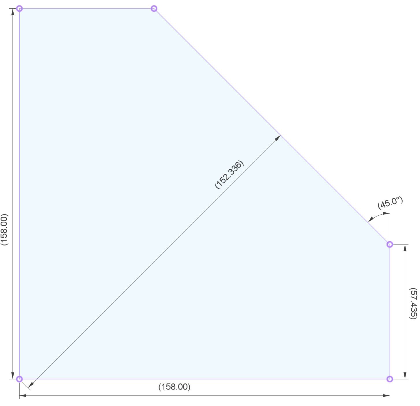
Assembly tools
- 2.5mm Allen key
- powered screw driver with Allen key head is optional but helps A LOT. I use my Ikea power drill with adjustable torque
- 10mm socket key/head can help for the pneumatic fitting
- small file can help for cleaning up the parts as needed
Assembly instructions
Assembly video and more photos are planned for the future. Until then you can use these instructions and use the YouTube playlist for reference as needed.
Most screws have no nuts and they tighten into the print. Do not overtighten any of them as this will destroy the printed parts.
- clean up any partially detached overhangs on the parts
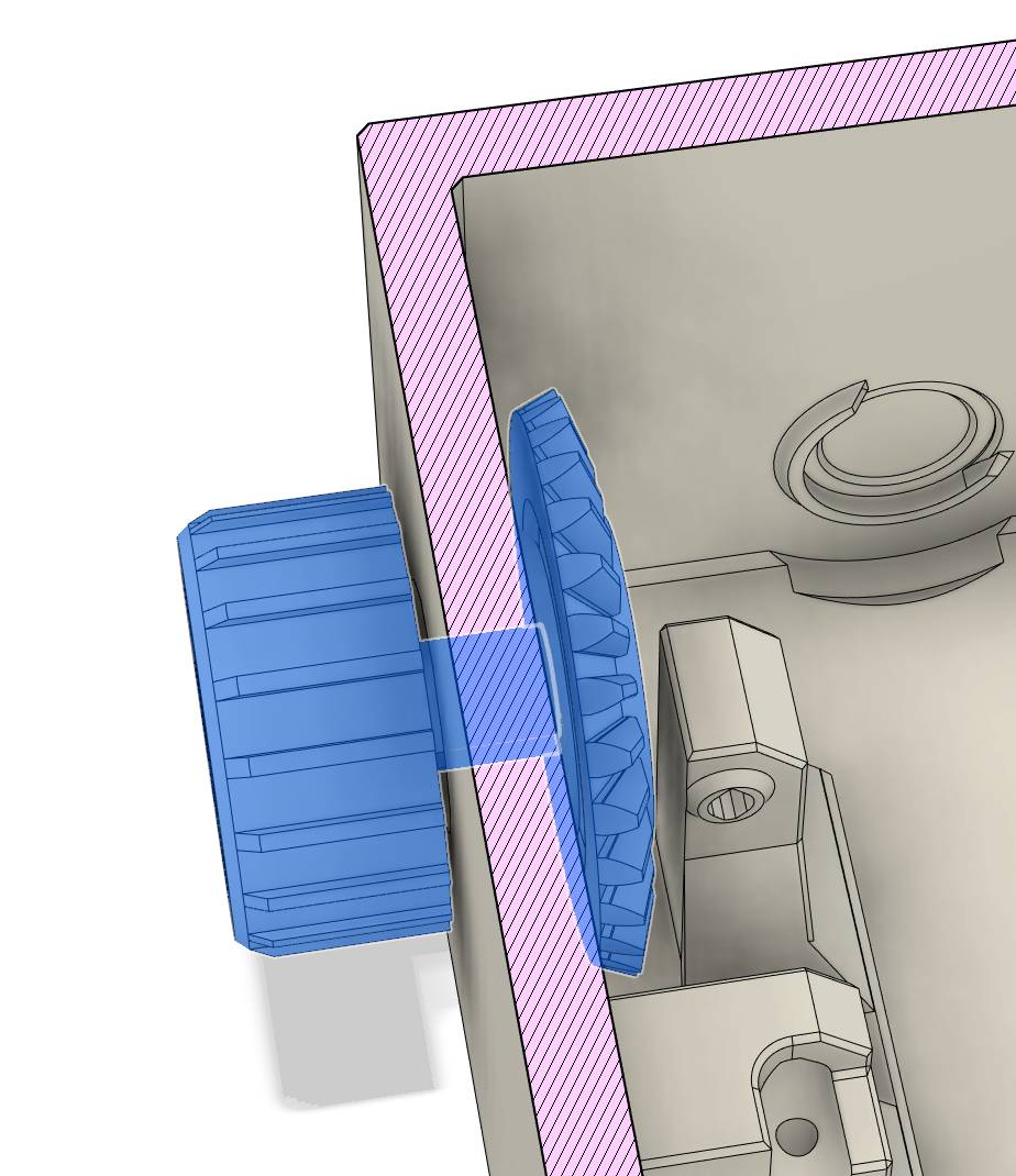 install the rewind knob using: 1 knob, 1 angled gear (with tooth on one side), 2 large bearings, 2 30mm screws:
- insert o large bearing inside the box in the rewind knob hole (from the inside)
- insert a large bearing on the knob
- align the angled gear with the hole inside the box, with its teeth pointing towards the inside. You should see the two screw holes from the outside looking through the hole
- insert the knob with the bearing in the knob hole of the box
- rotate the knob and align it with the wheel so that the screw holes of the wheel are visible through the holes in the knob
- screw in one 30mm screw in one of the holes through the knob and the angled gear. Do not tighten. There are no nuts here for the screws to grab on
- check the alignment for the second hole and screw in a second 30mm screw
- rotate the knob and adjust the screws by tightening/loosening as needed so that the knob rotates easily with no binding, but with no play at the gear, and the gear rotates somewhat uniformly and not looking wobbly (remember that there are no nuts so don’t overtighten)
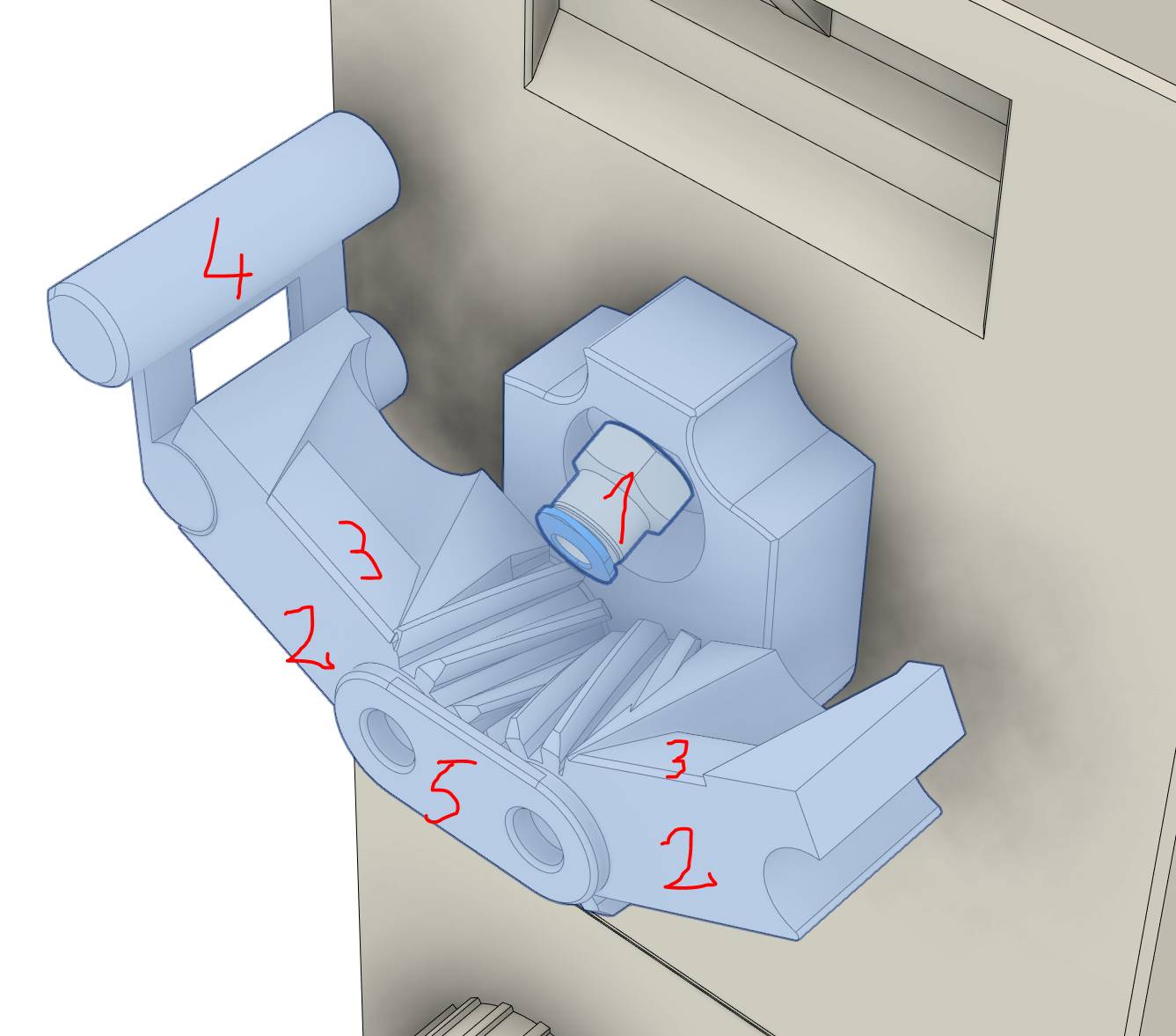
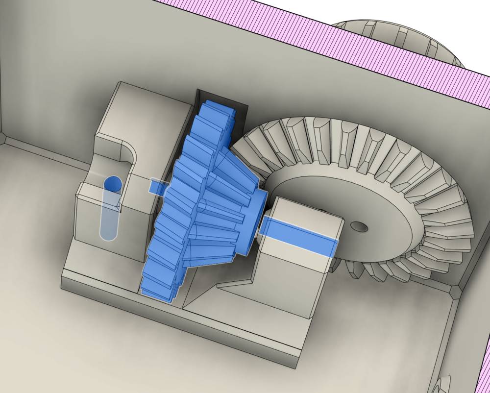 install the double gear using: 1double gear, 2 small bearings, 1 30mm screw, 1 12mm screw:
- insert both bearings at the ends of the gear, making sure they are aligned with the hole and are inserted as far in as there is room
- align the gear in place inside the box, smaller teeth facing the already installed gear
- insert the 30mm screw from the side and through the gear
- rewind knob should easily engage this new gear
- screw in the 12mm screw to prevent the larger screw above from coming out
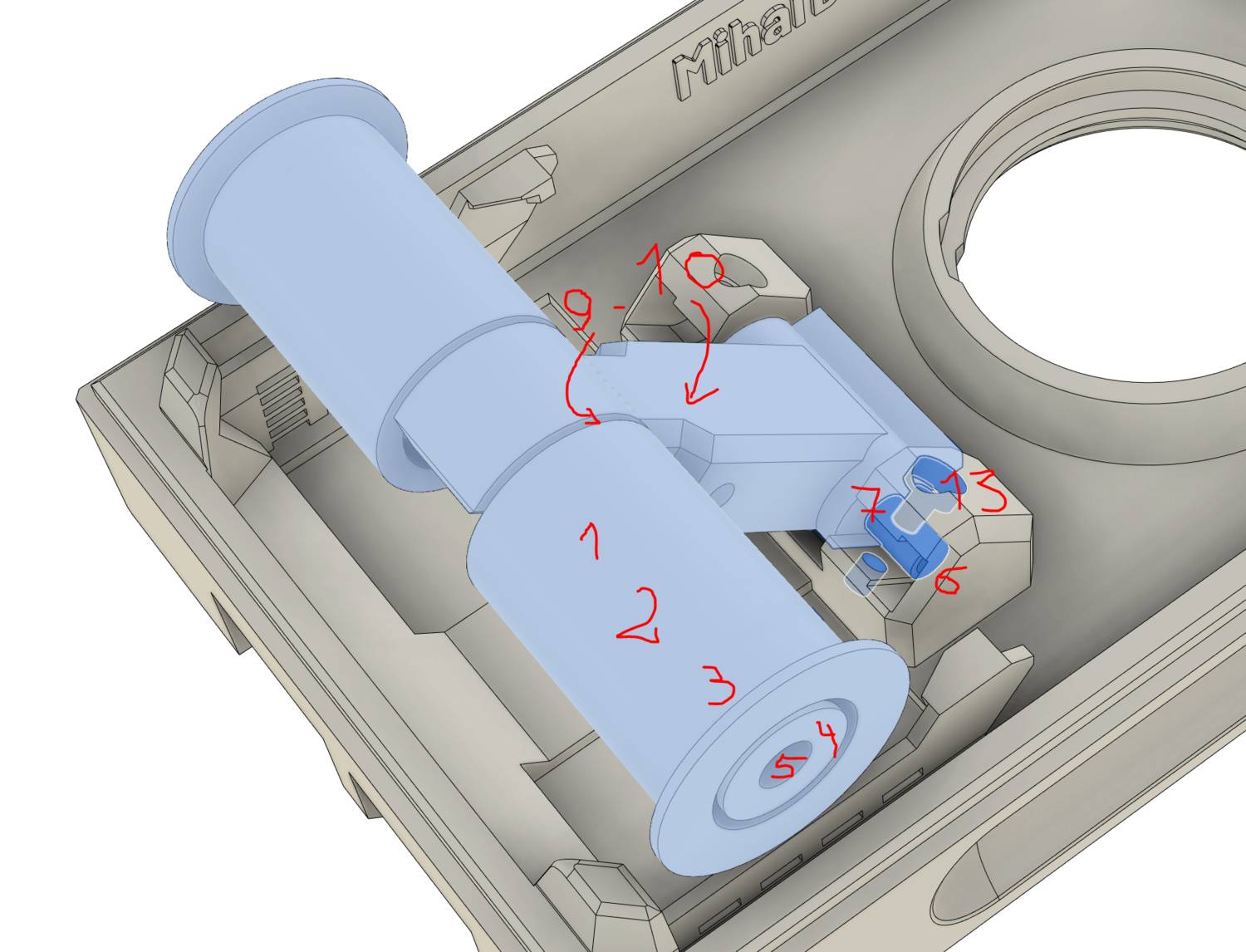
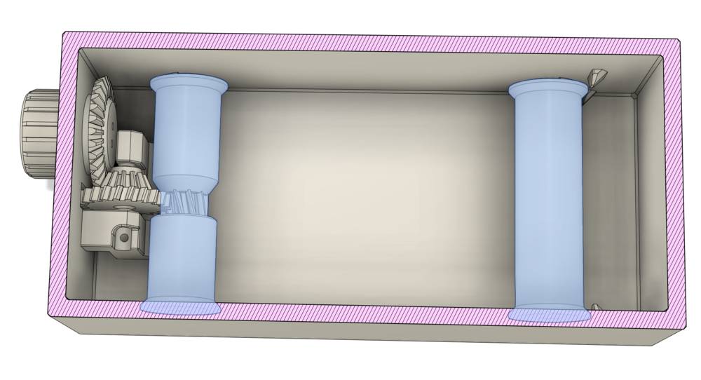 install lower rollers using: 1 long roller, 1 long roller with gear in the middle, 4 medium bearings, some anti-slip tape:
- add anti-slip tape on the geared roller spanning the round section (except for the gear in the middle). This allows for the rewind knob to work much better. Painter’s tape works. In addition, you may choose to add tape to all the other rollers to reduce noise
- add 2 bearings at the ends of the geared roller and insert it into place touching the already installed gears. It’ll take some force as the space is undersized. I try sliding it in with both ends at once as one end first didn’t work for me. The rewind knob should rotate the roller when turning it in the rewind direction
- add 2 bearings at the ends of the simple roller and insert it in its space across from the previous one
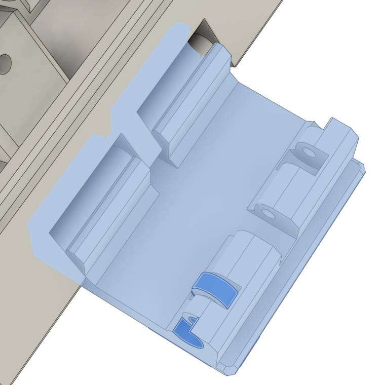
 install the filament exit valve using: 6 printed parts, one PC4-M10 pneumatic fitting, 2 40mm screws, 1 20mm screw, 2 12mm screws, 2 square Nuts
- screw in the pneumatic fitting in the valve back plate using a 10mm socket key
- insert the two airlocks on the part above. Make sure they align at the top when closed
- stick some bits of P-shaped or D-shaped adhesive door sealing rubber on the two airlocks where they meet
- position the lock at the top and fix in place with a 20mm screw
- put the cover plate over the two airlocks
- use the two 40mm screws and two square nuts to fix the entire assembly to the box. Nuts go inside the box in the square spaces. Do not tighten
- use the two 12mm screws from the inside of the box to further fix the assembly in place. These are not shown in the picture. Do not tighten
- make sure the filament path is aligned between the box and the outer assembly and gently tighten the 4 screws
 install the lid rollers using: 2 tee arms, 4 rollers, 4 roller caps, 4 screw sleeves, 8 12mm screws, 4 16mm screws, 8 medium bearings, 2 magnets:
- insert one bearing on one arm of a tee arm
- insert one roller on the arm with the larger end on the outside
- insert a bearing inside the roller above
- add a roller cap in the remaining hole
- screw in a 12mm screw through the cap. Do not tighten so that the roller can rotate with ease
- screw one 16mm screw into a small screw sleeve all the way. Note: if it turns out the tee arm can’t fit well or cannot freely move later because these sleeves are too tight, then you can try skipping these sleeves and I’ll be looking into a better solution
- screw the screw above into the side of the tee arm
- repeat steps 1-7 for the other side
- insert a magnet into the lid in one of the round cutouts towards one of the ends
- insert another magnet into the tee arm so that the two magnets will repel each other
- hold the magnet inside the lid with a slim tool like a screwdriver so that it doesn’t flip
- insert the tee arm in the lid with the magnet facing down, making sure the magnet doesn’t come out or flip. This part is tricky as the magnets will tend to flip when near each other
- fix the tee arm in place with 2 12mm screws
- repeat steps 1-13 for the other tee arm
- (optional, I sometimes skip these ones) add gaskets to the base and hygrometer cutout:
- 4-5mm wide adhesive gasket is needed. You can cut a W-shaped 9mm gasket in two on its length for this
- install the gasket at the top of the large box on the horizontal flat inner surface
- if using hygrometer, install gasket on the inside of the hygrometer cutout
 install hinges and hygrometer using: 2 hinge prints, 4 tiny printed wheels (same dimensions as the smallest bearings), 4 16mm screws, hygrometer
- insert one wheel into a hinge
- screw a 16mm screw through the wheel
- repeat steps 1-2 for the other side
- clip the hinge onto the lid
- repeat steps 1-4 for the other hinge
- if using the hygrometer, clip it inside the lid so that it doesn’t protrude above the lid surface
- try out the hinges by locking the lid to the box
- installing windows using: 1-2mm transparent panels and thick 6mm double-sided tape or silicone
- there is a version of the box without windows, in which case skip the rest of this section
- peel off the protection from one side of each panel (if any)
- if using tape, make sure it’s about 1mm thick to compensate for uneven print surface and about 6mm wide. 8mm might fit but will be visible from the outside. Stick the tape all around the perimeter of the peeled off surface from the panels. Make sure no gaps are left at the corners. Peel off any protection on the tape
- if using silicone, apply a continuous line of silicone around the perimeter of the panel, on the peeled off surface. Stay within 7mm of the edge of the panel. The box has a channel that can take excess silicone so that it doesn’t bleed into the visible area
- stick the panels on the inside of the box in the recess press firmly. If using silicone let it dry and harden in a ventilated area
- peel off the remaining panel protection (if any)
 add desiccant cages using: 4 square cages with lids, 1 long cage with lid, ~100g of silica or molecular sieve or other desiccant
- make sure all lids can easily be clipped onto the cages and can easily be removed by grabbing from the sides (not from the ends!). If needed use a file to slightly trim off bad box faces and lid clips
- make sure lids cannot fall off on a strong shake. If they do, you may have to reprint these parts with more XY compensation so the lids stay more firmly in place
- if the silica has small particles you’ll have to put it through a rough sieve to remove the tiny particles that could fall through the cage slits. I plan sharing such a sieve that can be 3D printed
- fill all cages with desiccant and close the lids. Shake them while upside down so that any leftover small particles come out
- any small particles that could fall and get stuck on the filament risk entering the hotend and produce a clog
- install the long cage at the bottom of the box
- install the 4 square cages in the lid, inserting them back-first under the rollers and then pushing them down
- adding tubes and doing final checks with 3mm ID 4MM OD PTFE tube
- use a 12cm (5”) piece of tube for the inside of the box. This helps reduce friction, BUT does not work with spools with holes on the sides (it jams), so for spools with cutouts on the side use a shorter piece of tube instead, of about 3-4cm (1.5”)
- insert a spool of filament with the end pointing towards the exit valve
- insert the end of the filament through the piece of tube and then insert it through the exit valve. This piece helps avoiding jams for wide spools with bad winding where loops can get stuck behind each other, so push it into the exit valve
- lock the lid into place
- make sure you can easily pull the filament out by hand and that you can rewind the spool back using the rewind knob. Don’t rewind the filament all the way into the box to avoid tangling!
- use a long tube on the outside of the box to the printer in a reverse Bowden setup so that the box is not pulled towards the printer and there are no sudden pulls by the print head moving on the X axis. Make sure the tube is somewhat straight as loops or tight turns will cause friction
- when not using the spool, rewind the filament back and then lock the valve so that the tip of the filament is being fixed in place and cannot fall into the box
- fill in the feedback form
Shortcomings
It requires a well calibrated printer. Skewed parts may not fit and low print quality can leave small holes through which humidity will creep in, or lid may not close properly, even if using mesh bed leveling on a skewed printer.
It’s not easy to source and assemble.
It’s not cheap. Takes a lot of parts, material, and time to assemble.
Not perfectly sealed. In my initial test I had to replace my silica gel after a month. Filament tends to be a bit porous, so it won’t perfectly seal the box. Day/night temperature variation will force a bit of air in and out no matter what. In my preliminary test humidity reached 20% after one month. For highly hygroscopic materials you should use a different box.
It can be a bit noisy when printing very fast or rewinding.
It’s likely that cardboard spools won’t work well.
No active heating, although I doubt any commercial heated dry boxes achieve any useful heating level for drying, and they don’t offer any sealing. I dry my filament separately in a dehydrator. A lot of filaments come moist from the factory despite the included silica pack, in which case you have to dry it in a dehydrator or other device. A dry box will not dry your filament.
The strong magnets + printed parts tolerances can cause a bit of friction for the filament being pulled. This is amplified when the spool is not perfectly round and has uneven points on the outside rolling surface. One solution is to use smaller, weaker magnets (not recommended for MMU2S use as there’s higher risk of windings escaping the rollers and causing a jam).
PTFE tubes used in a reverse Bowden setup (recommended) tend to amplify whatever friction there is inside the box (from the point above). I’m using 3mm ID tubes which reduce this issue to some extent.
Customization
To further customize the box using your favorite CAD software, download the STEP files below. Feel free to share your mods with the world.
DryBox STEP files